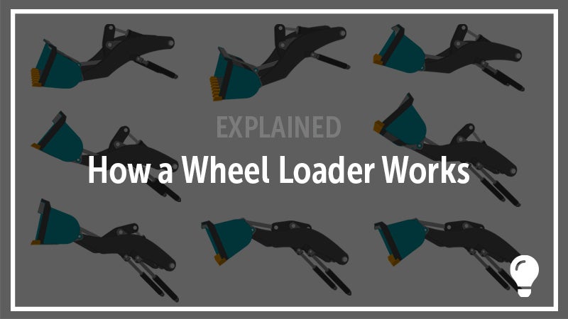
How A Wheel Loader Works: Wheel Loader Lift Arm Animation, Diagram, and Pictures
Across construction sites, farming and mining operations, waste management, demolition, or any worksite where materials are being loaded or transported, you’ll often find a hard-running wheel loader at work. This iconic machine is at the heart of worksites around the world — and rightfully so. Today, we’ll take a quick look at this machine, how its arm works, and what functions it performs to understand why it earned such an well-held place in our worksites.
What Are the Advantages of a Wheel Loader?
The design of a wheel loader offers a number of advantages and explains why it is so widely put to work across industries. Some of the advantages offered by a wheel loader are a strong versatility to perform a diverse set of jobs, high maneuverability to move around a worksite nimbly and swiftly, a simple design that can lead to reduced maintenance costs, less impact on working surfaces than other machines, and a wide range of sizes and attachments to fit numerous applications.
Though the basics of a wheel loader are often the same — four wheels, a cab for the operator, an attachment at the front — wheel loaders can be found in a number of different sizes and setups. Different attachments offer new tools for working with materials, a wide range of sizes are designed for certain applications, articulation offers more maneuverability, and other customizations fit specific circumstances. One of the most prominent differences in wheel loaders is how lifts are loaded and managed by the loader’s arm with the most common designs for the arm and its linkage being Z-bar linkage and parallel-lift linkage.
What is Z-bar linkage?
The Z-bar linkage design connects the bucket to the machine through a bucket cylinder, bucket links, and a bellcrank in the center of the loader arm. The formation of these parts in a “Z” shape gives the design its name. This is the traditional and original linkage design for loaders.
Advantages of Z-Bar Linkage
- Less connections and simpler design to maintain
- Generally greater power in digging
Disadvantages of Z-Bar Linkage
- Bellcrank and bucket cylinder can obstruct operator’s view
- Bucket will rotate as boom is raised and lowered, increasing the difficulty of maintaining a load level with the ground
What is parallel-lift linkage?
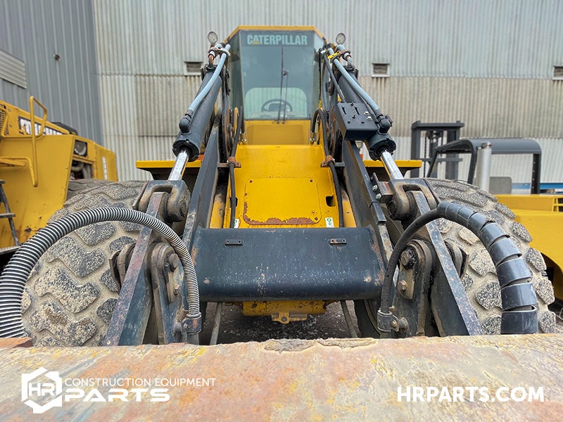
A parallel-lift linkage design separates the work of the bucket cylinder into two cylinders mounted on each arm of the loader’s boom. Connections to the bucket are also handled by multiple links, often connected in certain ways to refine how parts will rotate.
Advantages of Parallel-Lift Linkage
- Better visibility through a cleaner line of site to the bucket
- Level lifting as the boom is raised and lowered, ideal for loading delicate material with forks or other attachments
Disadvantages of Parallel-Lift Linkage
- A more complex design with more connections and more parts
- Less raw breakout power for power intensive tasks
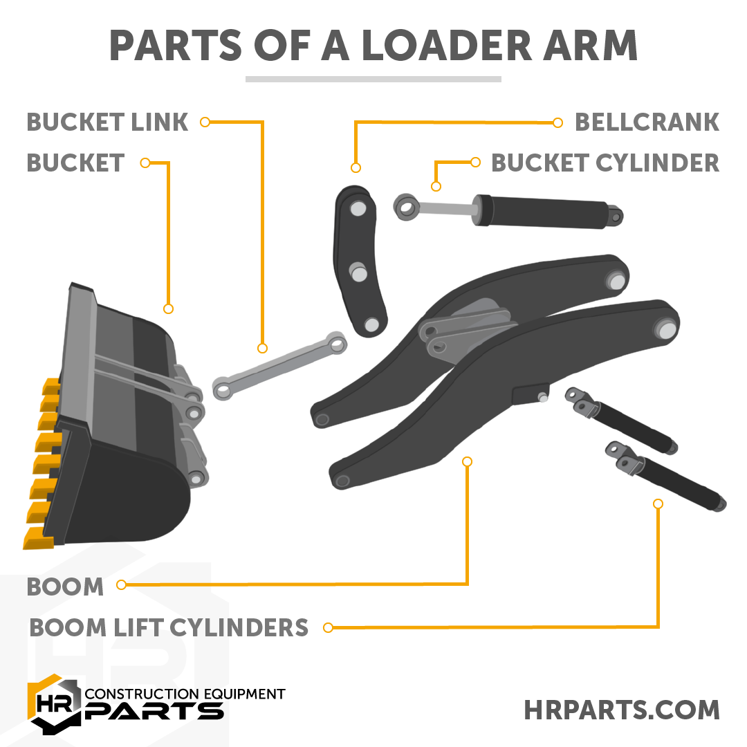
What Are the Parts of a Wheel Loader Arm?
Bucket
All the parts of the wheel loader lift arm are designed to work together to allow the operator to control the action of the bucket as they push, carry, dig, lift, and dump materials. Loader buckets are designed in a wide range of configurations with aspects of the bucket chosen to match the application from loading heavy rocks to digging large pits to filling trucks to even pushing snow.
Bucket Cylinder
Depending on the linkage design, either one or two cylinders will be responsible for tilting the bucket to scoop or dump materials. These heavy duty bucket cylinders must be rigorous enough to handle heavy materials and an often heavy bucket as the bucket routinely fills and dumps.
Boom
The wheel loader boom consists of two, large and heavy-duty interconnected arms that pivot at a connection to the machine. The length of the boom determines the height at which material can be dumped so a machine (and its boom length) should match the work it's intended to perform and how it will work with other machines on the jobsite.
Boom Cylinder
Raising and lowering the boom allows the operator to load trucks, pile materials, and perform other tasks. To facilitate these lifts, two boom cylinders act in unison to raise and lower the boom and since the combined weight of the load, the boom, and the bucket can be considerable these cylinders must be designed to match the work the machine is designed to perform.
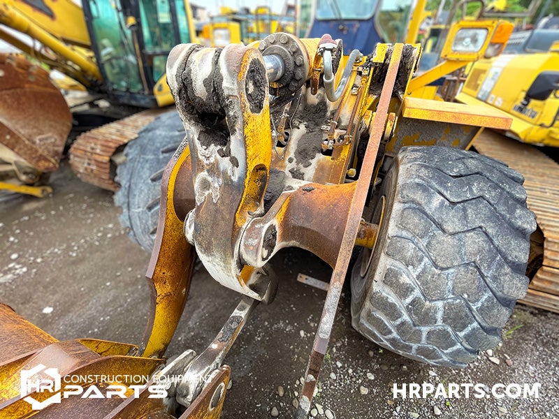
Bellcrank
In a loader with Z-bar type linkage, one of the pieces of the linkage is a large bellcrank. Connected to the bucket cylinder and the bucket linkage and with a pivot point at its center, the bellcrank is a basic lever that allows the operator to control the bucket. Extending the bucket cylinder rotates the top of the bellcrank forwards causing the lower part to rotate towards the machine. Through the cylinder’s connection with the linkage to the bucket, this action pulls the top of the bucket towards the machine and forces it to rotate the bucket up and into a scooping motion.
In reverse, retracting the bucket cylinder rotates the bellcrank towards the operator and initiates a dumping action with the bucket.
Bucket Linkage
Often called “dog bones” because of their shape, bucket links connect the bucket and the bellcrank through a set of pins. While the design of bucket links is not overly complicated, the constant forces under which they work and the friction of moving parts can force them to wear and warp without proper maintenance.
Pins and Bushings
To facilitate the raising and lowering of the loader’s boom and the rotating of the loader’s bucket, a number of parts need to be connected together in a way that still allows for some independence in movement. Pins, pin holes, and pin ears at intersections connect parts of the loader arm together while bushings or bearings allow for smooth movements and reductions in friction. Because of the repeated movements at these intersections they must be inspected frequently to ensure they are working properly and not wearing into the larger parts.
What Are the Attachments for a Wheel Loader?
The buckets on a wheel loader can be as diverse as the types of materials they are commonly working with from different size buckets to different teeth and cutting edges to reinforcements and how substantial the design of the bucket is. These variations in bucket design allow operators to focus on job specific goals like ensuring the bucket will stand up to rugged materials or trading weight for increased efficiency or fitting the cutting edge to the materials that the machine will dig.
Increasingly though on a worksite you’ll find more than just buckets at the end of a wheel loader arm. These job-specific attachments can transform a wheel loader into a diverse tool carrier and make a wheel loader an even more valuable asset on a worksite.
Some of the most common attachments are forks for loading pallets, snow blowers and blades for working with snow, couplers for quick changing attachments, augers for digging post holes, brooms for sweeping roads, and more.
Since their invention by Volvo in 1954, wheel loaders have become a staple on worksites around the world. After this short look at how they work and what they can do, it should be clear why. While their simplicity can shorten the learning curve for operators, it's at the hands of an expert operator where their digging, loading, and transporting power can be hard to match.
Hopefully, after this short article you’ve found an even greater appreciation for wheel loaders. If, however, you’re in search of a parts solution for your own wheel loader and you’ve found your appreciation for it waning — give our Parts Specialist team a call. They’re dedicated to ending your search and solving your problems. As a top dismantler of wheel loaders and with connections to our national parts network, one quick call can often get you to a solution, quickly and simply.
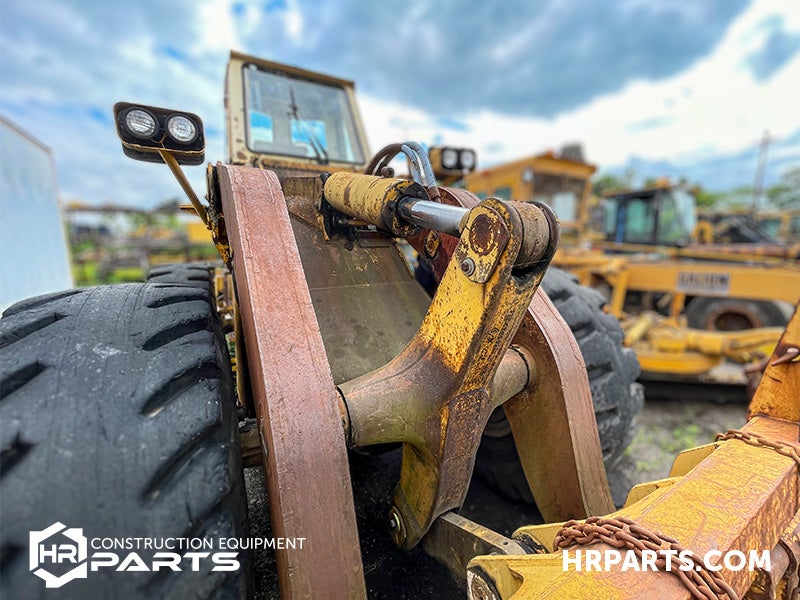
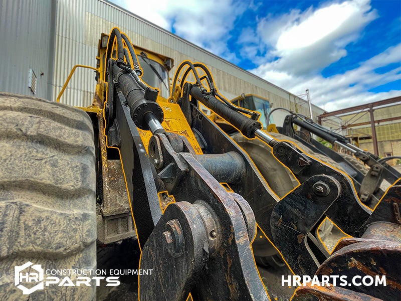
Wheel Loader Arm Image Gallery